To download the Operating System tOSh, you can do it from the Resources section of this same site.
Parts
This series of articles will have the following parts:
- Part I - Bootloader
- Part II - Stage 1 <— You’re here
- Part III - Jumping to C
- Part IV - Interrupts
- Part V - Filesystem and Floppy Drive Driver
- Part VI - Booting on different types of machines
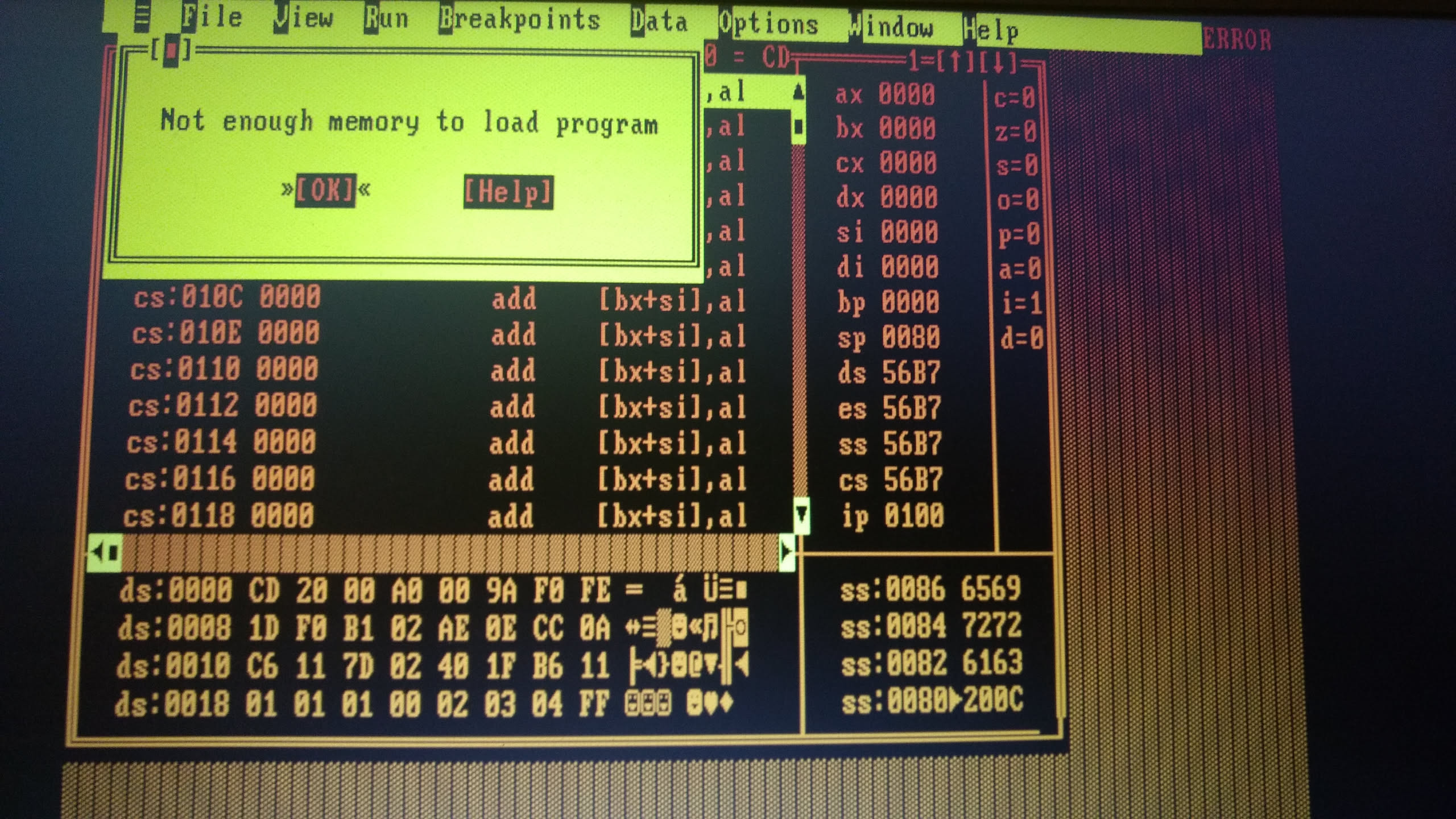 Turbo Debugger - Not Enough Memory
Stage I - From Real Mode to Protected Mode
We’re in the Real Mode. The last thing we did was jump to another memory location where we should have been able to copy another piece of binary code that we’ll call stage1, which we took from a sector of the Floppy where we’re compiling and storing the entire bootloader, as we saw in the first part of this series, and now it’s time to see what we do with control of our CPU. This reminds me of some gaucho-style sextillas by our beloved Diego Silicio, gaucho of the cathode:
Atendiendo la obligada,
no se haga el distraído
no se olvide la pavada,
ni se pierda el protegido,
que es cuestión de buen formato,
¡memorí laiaut bendito!
Translation:
Paying heed to what must be done,
don’t go pretending you’re unaware,
don’t forget the little things,
nor lose sight of Protected Mode,
for it’s all a matter of good format,
¡memorí laiaut be blessed!
Explanation: This is a sextilla gauchesca, a six-line gaucho-style verse. The humor comes from forcing technical terms into the rhythm and rhyme of traditional gaucho poetry. In particular, “memorí laiaut” is a deliberately gauchified pronunciation of “memory layout.” That joke doesn’t really survive in English, so the original is kept alongside the translation.
To better understand what we’re going to do, and how we’re going to configure the CPU so that it changes Mode, we need to understand our Memory Layout (memorí laiaut) and where we’re deciding almost arbitrarily –and this is very, very important, the "almost" arbitrary part– where we’re going to copy everything into memory, this very same stage1.bin which we load from disk into memory and jump to, and where we start running with the last instruction of the bootloader: jmp 0x9000.
First, it’s worth explaining that the Memory Layout of x86 machines is already defined, and there are memory addresses that have overlays with components and peripherals that we use to communicate with them. This means that we can’t simply use sections of memory because they’re being used by other devices and by the CPU to communicate with each other, by the BIOS at 0040:0000h, and also to interface with the user. We’ll take as an example the table we can find in the document Physical Memory Layout of the PC and mix it with our layout. The idea is, first of all, to avoid overwriting these memory regions that don’t belong to us and, on the other hand, to find a gap where we can write our own code into memory for stage1.bin and, in the future, our kernel.bin. We should have enough space for everything without overwriting anything.
| linear memory range | real-mode address range | memory type | usage |
|---|---|---|---|
| 0- 3FF | 0000:0000-0000:03FF | RAM | real-mode interrupt vector table (IVT) |
| 400- 4FF | 0040:0000-0040:00FF | RAM | BIOS data area (BDA) |
| 500- 9FBFF | 0050:0000-9000:FBFF | RAM | free conventional memory (below 1 meg) |
| 0x9000 + (512bytes * 4 sectors) | 0900:0000 – 0900:07FF | RAM (stage1.bin) | we get in here, below the first megabyte of memory |
| 0x10000 + (512bytes * n sectors) | WHO THE FUCK CARES! | RAM (kernel.bin) | by this point, we should already be in [Protected Mode] |
| 0x80000 | WHO THE FUCK CARES! | RAM (stack) | The stack that will be used by the kernel and our programs |
| 9FC00- 9FFFF | 9000:FC00-9000:FFFF | RAM | extended BIOS data area (EBDA) |
| A0000- BFFFF | A000:0000-B000:FFFF | Video RAM | VGA framebuffers |
| C0000- C7FFF | C000:0000-C000:7FFF | ROM | video BIOS (32K is typical size) |
| C8000- EFFFF | C800:0000-E000:FFFF | NOTHING | |
| F0000- FFFFF | F000:0000-F000:FFFF | ROM | motherboard BIOS (64K is typical size) |
| 100000- FEBFFFFF | RAM | free extended memory (1 meg and above) | |
| FEC00000- FFFFFFFF | various | motherboard BIOS, PnP NVRAM, ACPI, etc. |
Keeping all of this in mind, we can start looking at some code, stage1.asm:
; ----------------------------------------------------
; tOSh Operating System, Huh?                 (c) 2019
; stage1.asm                                  by toshi
; $ nasm -D KERNEL_FIRST_SECTOR=$KERNEL_FIRST_SECTOR \
;   -D KERNEL_SECTORS=$kernel_sectors \
;   -f bin -l stage1.lst stage1.asm -o stage1.bin
; ----------------------------------------------------

bits 16
org 0x9000                  ; we copied sector 2+ here!
[map symbols stage1.map]    ; create a stage1.map file for offsets checking

KERNEL_OFFSET equ 0x10000
STACK_ADDRESS equ 0x80000
Everything that gets assembled will be in 16 bits relative to org 0x9000. Additionally, we’re going to create a symbol map that will help us see the offsets of the functions if we need them during development, using the map symbols directive.
Among its various advantages, the one I find most useful is being able to keep track of the equ, function names, and their memory locations after being assembled, even when stage1.asm has several %includes.
map symbols stage1.map produces a file that looks something like this:
- NASM Map file ---------------------------------------------------------------

Source file:  stage1.asm
Output file:  stage1.bin

-- Symbols --------------------------------------------------------------------

---- No Section ---------------------------------------------------------------

Value     Name
00010000  KERNEL_OFFSET
00080000  STACK_ADDRESS
00000008  CODE_SEGMENT
00000010  DATA_SEGMENT
000B8000  VRAM


---- Section .text ------------------------------------------------------------

Real              Virtual           Name
            9023              9023  prepare_protected_mode
            903B              903B  load_kernel
            9052              9052  load_kernel.next_sector
            9070              9070  load_kernel.destination_ok
            908A              908A  load_kernel.done
            908F              908F  load_error
            909A              909A  kernel_sectors_remaining
            909C              909C  error_hang
            90A7              90A7  init_protected_mode
            90E7              90E7  protected_mode_msg
            9108              9108  kernel_load_fail_msg
            9121              9121  kernel_load_msg
            9148              9148  gdt_start
            9150              9150  gdt_code_segment
            9158              9158  gdt_data_segment
            9160              9160  gdt_descriptor
            9166              9166  gdt_end
            9166              9166  enable_A20
            9196              9196  a20wait
            919D              919D  a20wait2
            91A4              91A4  asm_print_protected
            91AA              91AA  asm_print_protected.loop
            91BD              91BD  asm_print_protected_end
            91BF              91BF  asm_print_hex
            91D0              91D0  asm_print_hex.loop
            91E2              91E2  asm_print_hex.digit
            91E5              91E5  asm_print_hex.write
After changing the background to gray -you can see this in the OS source code in the Resources section - we make a call to load_kernel, which essentially copies the kernel binary (which is still a work in progress) to the arbitrary memory location 0x10000, defined by the KERNEL_OFFSET equ 0x10000 above.
load_kernel:
    ; ---------------------------------------------------------
    ; Load KERNEL_SECTORS sectors from floppy into 0x10000
    ;
    ; Floppy geometry:
    ;   80 cylinders
    ;   2 heads
    ;   18 sectors per track
    ;
    ; Kernel starts at KERNEL_FIRST_SECTOR
    ; check build.sh for sector calculations
    ; ---------------------------------------------------------

    push ax
    push bx
    push cx
    push dx

    ; Destination = 0x10000 + n bytes, ES = 0x1000, BX = copy n bytes offset
    xor bx, bx
    mov ax, 0x1000
    mov es, ax
One thing worth highlighting in this list (phuá, "list" I called it, we’re back in the 80s!) is how careful you have to be with something I’m going to call "segment arithmetic", because I don’t really know what else to call it. Every time, in 16 bits, you have to write something to memory, you always have to take into account the segment you’re going to operate in and how the instructions use it or don’t, as well as the relationship between the "logical" and physical memory address, always keeping the following formula in mind:
Physical Address = (Segment * 16) + Offset
All of this has to do with how to address more than 64 kilobytes (that is, 2^16 is 16 bits) when physically you have one, two, or more megabytes. Well, the guys at Intel solved it this way, and it brings quite a few headaches because this arithmetic means that addresses aren’t unique and overlaps are generated. I copy the Kernel into memory like this and then jump to [Protected Mode], where this problem disappears. And when I was trying to copy a binary into memory, I used the BIOS functions to copy the kernel from the floppy to memory because I wanted to support the 286, which has a pretty crappy protected mode, and then things got complicated and ended up like this.
load_kernel works, and once I managed to get it to copy the kernel and actually work, I didn’t want to touch it anymore.
If you more or less understand exactly what I’m doing in:
    xor bx, bx
    mov ax, 0x1000
    mov es, ax
Where I’m preparing the copy, you’ll see that instead of stopping at 0x10000, which would be the logical thing to do, I stop at <--> Segment:Offset <--> 0x1000:0x0000 <--> ES:BX. I’m deliberately abusing notation so that it "REALLY STANDS OUT" what I’m saying, because this is FUNDAMENTAL to understanding why things never end up in memory where you expect them to.
In other words, because of everything we’ve said:
Physical Memory: 0x10000 (five zeros) <—> 1000:0000 (four zeros, four zeros)
And why does the segment go in ES? When you call INTerrupts or certain instructions, they use SEGments to operate. It’s a convention, and the details are in the Intel manuals and Ralf Brown’s Interrupt List.
pues le digo, mi ingeniero
que tiene la segmentación
pa' que no falte ocasión
y no se le pase el viaje
a esos bites ni el anclaje
ni una horrible excepción
Translation:
well, I tell you, my engineer
that’s what segmentation is for
so no opportunity goes to waste
and the journey doesn’t pass you by
those bites nor their anchorage
nor one horrible exception
Explanation: This is another sextilla gauchesca. The rhyme and rhythm are deliberately built around technical vocabulary. The particularly funny bit is “bites”: it is a gaucho-style deformation of bytes, while “anclaje” (anchoring) continues the image of keeping those bits/bytes properly anchored. The exact rhyme and wordplay cannot be reproduced naturally in English, so the original is kept alongside the translation.
What follows in the load_kernel function is a standard routine for copying sectors from the floppy disk to memory:
    ; Current CHS
    xor ch, ch                  ; cylinder = 0
    mov dh, 0                   ; head = 0
    mov cl, KERNEL_FIRST_SECTOR ; sector

    ; Number of sectors remaining
    mov word [kernel_sectors_remaining], KERNEL_SECTORS

.next_sector:

    cmp word [kernel_sectors_remaining], 0
    je .done

    ; BIOS read: exactly ONE sector
    mov ah, 0x02
    mov al, 1
    mov dl, 0                   ; floppy drive A:

    int 0x13
    jc load_error

    ; ---------------------------------------------------------
    ; Advance destination by 512 bytes
    ; ---------------------------------------------------------

    add bx, 512

    ; If BX wrapped around, advance ES by 0x1000
    ; because 0x1000:0000 -> 0x2000:0000
    jnc .destination_ok

    mov ax, es      ; yuck!
    add ax, 0x1000  ; we are going to leave all this
    mov es, ax      ; segment:offset madness very soon!

.destination_ok:

    ; One less sector to load
    dec word [kernel_sectors_remaining]

    ; ---------------------------------------------------------
    ; Advance CHS
    ; ---------------------------------------------------------

    inc cl                      ; next sector

    cmp cl, 19                  ; floppy has sectors 1..18
    jb .next_sector

    ; End of track -> next head
    mov cl, 1
    inc dh

    cmp dh, 2                   ; heads 0 and 1
    jb .next_sector

    ; End of cylinder -> next cylinder
    mov dh, 0
    inc ch

    jmp .next_sector


.done:
    pop dx
    pop cx
    pop bx
    pop ax
    ret


load_error:
    ; BIOS sets carry flag (CF) on error
    ; AX contains BIOS error information

    mov ebx, kernel_load_fail_msg
    call asm_print_protected

    jmp error_hang


kernel_sectors_remaining dw 0


error_hang:
        mov ebx, kernel_load_fail_msg
        call asm_print_protected
        jmp $       ; loop forever
                    ; Instruction Pointer is self (JMP IP)
Preparing Protected Mode
The Real Mode we’re in is some piece of crap from the ’70s/’80s, and here we are in 2019 still writing this kind of code, so we’re going to configure the CPU to switch from 16-bit mode to 32-bit mode.
For this, we have to do several things:
- Build a descriptor in the Global Descriptor Table or GDT
- Enable the A20 bus line
- Build an Interrupt Descriptor Table IDT (Update: keeping it in assembly wasa pain in the ass, so I moved it to the Kernel in C, and it’s covered in another article)
- Enable [Protected Mode] after configuring all of this through the control register cr0
- Jump to 32-Bit code
; Ok, we now try to switch to protected mode
prepare_protected_mode:
    cli                     ; disable interrupts

    lgdt [gdt_descriptor]   ; load the gdt_descriptor table in gdt.asm
                            ; with the lgdt (load GDT) instruction

    ; Fast A20 Gate 286+ ?
    ; using this Fast A20 gate resets the computer on 286
    ;in al, 0x92
    ;or al, 2
    ;out 0x92, al
    call enable_A20         ; so we try to use this neat function instead

    ; lidt instruction execution moved to C kernel!
    ;lidt [idt_descriptor]

    ;xchg bx, bx             ; magic bochs breakpoint

    ; protected mode 286+ ?
    ; we are NOT supporting 286!!!!!111 t_t
    ; tOSh it's 386+ -ONLY-
    ;    lmsw ax        ; pre-cr0 register is the 'msw' register in 286
    ;    or ax, 0x1     ; and this way you enable
    ;    smsw ax        ; protected mode, but cannot make it work,
                        ; don't know what I missed

    mov eax, cr0
    or  eax, 0x1            ; set the 32-bit mode (Protected Mode)...
    mov cr0, eax            ; into cr0

    ; the CODE_SEGMENT is defined in gdt.asm
    jmp CODE_SEGMENT:init_protected_mode        ; far jump!
What I’m going to explain here is an exaggerated superultraoversimplification of what you’d actually need to read from at least two of the six volumes that make up the Intel manuals, where everything you need to understand how to configure the CPU is explained in excruciating detail.
GDT
The GDT is a data structure used by Intel processors (32/64-bit) to define memory segments and permissions so that each of those segments can be written to, read from, and executed in every possible combination. It’s an array of 8-byte entries that looks like this in [tOSh]:
; https://wiki.osdev.org/GDT_Tutorial
; https://wiki.osdev.org/Global_Descriptor_Table
bits 32
db 'GDT'    ; GDT mark for bin
gdt_start:
    ; the first entry of the GDT must start with
    ; 8 null bytes

    dd 0x0
    dd 0x0

gdt_code_segment:
    ; this is the entry for the kernel address space
    dw 0xFFFF   ; limit 0:15 - 16 bits - 2 bytes
                ; (all will be pages of 4KiB, so take this into account)
    dw 0x0000   ; base  0:15 - 16 bits - 2 bytes
    db 0x00     ; base  16:23 - 8 bits - 1 byte
                ; Base address will be 0
    db 10011010b ; access byte - 8 bits - 1 byte
                 ; present bit: 1
                 ; privilege, 2 bits, 0 = kernel space, 3 = userspace
                 ; S: Descriptor type: enable for code/data segments, 0 for system segments
                 ; executable bit: 1
                 ; Direction bit/Conforming bit: 0, code only exec by priv lvl
                 ; RW (code segments read access, data segments always read, set for writing) : 1
                 ; Ac: accessed bit, set to 0 as recommended by osdev
    db 11001111b ; first flags then limit 16:19 / (1 byte) 1 nibble - 1 nibble
                 ; FLAGS (1st most significant nibble):
                 ; Granularity: 0 = 1 byte blocks, 1= 4KiB blocks (pages)
                 ; Size bit: 0 = 16 bit protected mode, 1 = 32 bit protected mode
                 ; next to bytes in the nibble must be zero
                 ; 2nd nibble: limit 16:19
                 ;
    db 00000000b ; base 24:31 - 8 bits - 1 byte

gdt_data_segment:
    ; this is the entry for the kernel address space
    dw 0xffff   ; limit 0:15 - 16 bits - 2 bytes
    dw 0x0000   ; base  0:15 - 16 bits - 2 bytes
    db 0x00     ; base  16:23 - 8 bits - 1 byte
    db 10010010b ; access byte - 8 bits - 1 byte
    db 11001111b ; first flags then limit 16:19 / (1 byte) 1 nibble - 1 nibble
    db 00000000b ; base 24:31 - 8 bits - 1 byte

; gdt_tss_segment:
;     ; this is the entry for the kernel address space
;     dw 0x0000   ; limit 0:15 - 16 bits - 2 bytes
;     dw 0x0000   ; base  0:15 - 16 bits - 2 bytes
;     db 0x00     ; base  16:23 - 8 bits - 1 byte
;     db 00000000b ; access byte - 8 bits - 1 byte
;     db 00000000b ; first flags then limit 16:19 / (1 byte) 1 nibble - 1 nibble
;     db 00000000b ; base 24:31 - 8 bits - 1 byte

; gdt_ldt_segment:
;     ; this is the entry for the kernel address space
;     dw 0x0000   ; limit 0:15 - 16 bits - 2 bytes
;     dw 0x0000   ; base  0:15 - 16 bits - 2 bytes
;     db 0x00     ; base  16:23 - 8 bits - 1 byte
;     db 00000000b ; access byte - 8 bits - 1 byte
;     db 00000000b ; first flags then limit 16:19 / (1 byte) 1 nibble - 1 nibble
;     db 00000000b ; base 24:31 - 8 bits - 1 byte

; gdt_user_segment:
;     ; this is the entry for the kernel address space
;     dw 0x0000   ; limit 0:15 - 16 bits - 2 bytes
;     dw 0x0000   ; base  0:15 - 16 bits - 2 bytes
;     db 0x00     ; base  16:23 - 8 bits - 1 byte
;     db 00000000b ; access byte - 8 bits - 1 byte
;     db 00000000b ; first flags then limit 16:19 / (1 byte) 1 nibble - 1 nibble
;     db 00000000b ; base 24:31 - 8 bits - 1 byte

gdt_descriptor:
    dw gdt_end - gdt_start - 1
    dd gdt_start

gdt_end:

; constants to be used by stage1.asm

CODE_SEGMENT equ gdt_code_segment - gdt_start
DATA_SEGMENT equ gdt_data_segment - gdt_start
;TSS_SEGMENT  equ gdt_tss_segment  - gdt_start
;LDT_SEGMENT  equ gdt_ldt_segment  - gdt_start
;USER_SEGMENT equ gdt_user_segment - gdt_start
A20
The A20 line is a physical representation of the 21st bit of any memory address. For compatibility reasons with earlier processors, Intel’s CPU designers "patched it together". To this day, on modern Intel-based processors, you still have to configure this mess that was made about 50 years ago.
Click on A20 and look up the full story of this entire processor-design and Intel subplot, because it’s absolutely worth it.
We could skip the whole lore by raising the bar of our Operating System for IBM PS/2+ PC Compatible computers using the method mentioned in osdev: Fast A20 Gate:
in al, 0x92
or al, 2
out 0x92, al
But we’d better include and call an a20.asm that I copied and pasted from some place in La Mancha, whose name I can’t remember.
Note: This is a reference to the opening line of Cervantes’ Don Quixote: “In a place in La Mancha, whose name I do not want to remember.” The original Spanish deliberately changes it to “somewhere in La Mancha which I can’t remember.”
cr0
    mov eax, cr0
    or  eax, 0x1            ; set the 32-bit mode (Protected Mode)...
    mov cr0, eax            ; into cr0

    ; the CODE_SEGMENT is defined in gdt.asm
    jmp CODE_SEGMENT:init_protected_mode        ; far jump!
We set bit 1 of the cr0 control register with an OR to enable [Protected Mode] and jump directly to the 32-bit code.
There are a whole bunch of other things that can be configured in the CPU, but we’ll leave the other available features and configurations as an exercise for the reader ;-).
A 32-Bit World
We (finally!) reach the world of 32 bits and the realm of linear memory addresses. We copy a "mysterious kernel written in C" into memory, but before we can use it, we have to obviously keep configuring the CPU, its segments in 32-bit mode, and the stack as well.
pHUN pHAKT: In criollo, we call the stack "The Stack".
Explanation: “Pila” has two meanings in Spanish. In computing, stack is translated as pila. But pila also means a battery/cell — the thing you’d call a battery in English or an Akku/Batterie in German.
So “en criollo le decimos ‘La Pila’” is also jokingly turning the technical stack into a physical battery. It works especially well because pila is such an ordinary Argentine word for a battery.
; ---------------------------------------------------------------------
; 32 bit code! now we are able to use 32 bit instructions at this point
; ---------------------------------------------------------------------
bits 32
init_protected_mode:
    ; and we need to setup the segments again
    ; with our previously configured GDT configuration addresses
    ; find gdt.asm and other %includes further in this listing
    mov ax, DATA_SEGMENT        ; defined in gdt.asm
    mov ds, ax                  ; data segment
    mov es, ax                  ; extended segment
    mov fs, ax                  ; fuck you segment
    mov ss, ax                  ; stack segment
    ;mov ax, USER_SEGMENT       ; in the future, maybe...
    mov gs, ax                  ; gorgeous segment <3
    ;mov ax, CODE_SEGMENT
    ;mov cs, ax                 ; TODO: why i didn't setup the code segment?
                                ;       while reviewing the code for the article
                                ;       I found this commented like years ago
                                ;       and I got startled. Maybe for another
                                ;       time...

    ;ret ; !!!!!
    ; set up the stack
    ;mov ebp, 0xf90000        ; 16MB RAM machine! this breaks old 86box / PCem Machines!
    mov ebp, STACK_ADDRESS    ; equ 0x80000 --> stack ~ 576KiB
    mov esp, ebp
One of the great debugging sessions that spawned chunks of ISABugger-Related-Code was figuring out why our kernel was blowing up, and it was exactly about setting up the stack correctly. As you can see in the asm, I was using the address 0xf90000 as the extended base pointer and extended stack pointer to define where our stack was going to live, and the VMs I was testing on didn’t have THAT much memory, causing me to go outside the boundaries and the CPU to throw an unrecoverable exception. Just one instruction and quite a lot of debugging time with bochs made me realize the error.
So now the stack lives approximately around 576KiB.
    ; [ a lot of debugging stuff ]

    ; PIC Remapping ! (now handled by kernel at pic.c)

    ; mov al, 0x11
    ; out 0x20, al        ; restart pic1
    ; out 0xa0, al        ; restart pic2

    ; mov al, 0x20
    ; out 0x21, al        ; pic1 now starts at 32
    ; mov al, 0x28
    ; out 0xa1, al        ; pic2 now starts at 40

    ; mov al, 0x04
    ; out 0x21, al        ; setup cascading
    ; mov al, 0x02
    ; out 0xa1, al

    ; mov al, 0x01
    ; out 0x21, al
    ; out 0xa1, al        ; listo!


    ; ; IRQ1 = keyboard
    ; mov al, 0xFD
    ; out 0x21, al

    ; ; mask slave PIC
    ; mov al, 0xFF
    ; out 0xA1, al

    ; the kernel is the responsible for enabling
    ; the interrupts!
    ; the kernel now initializes IDT --> THEN STI()
    ;sti ; enable interrupts!

    jmp  KERNEL_OFFSET ; execute kernel code
And the final jmp. Everything else was commented out because I moved it to the kernel written in C, which we’ll jump to in the next article.
Recapping, basically what we did was copy the kernel that we don’t actually have yet, jump to [Protected Mode], and once there, set up the 32-bit stack and finally jump to the C Kernel Entrypoint.