To download the Operating System tOSh, you can do it from the Resources section of this same site.
Parts
This series of articles will have the following parts:
- Part I - Bootloader <— You’re here
- Part II - Stage 1
- Part III - Jumping to C
- Part IV - Interrupts
- Part V - Filesystem and Floppy Drive Driver
- Part VI - Booting on different types of machines
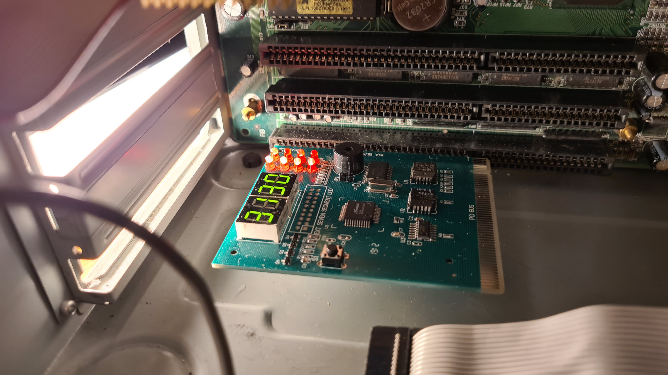 ISA POST Tester Card
Preface
Another Operating System? Yes. Why? Because I can. Amazingly, I have free time! And since this is part of a larger project, in a few months, when I have enough time again to review it, I’m going to need a summary and documentation, and writing this article somehow will help me keep everything in one place so I can refer back to it later.
What’s that project? Are you going to compete with the Kernel of Linux? Are you going to try to replace Windows with your own? No. Not at all.
In fact, I think it’s quite difficult to do something like this individually these days, and whatever one might be able to accomplish alone couldn’t get much further than what Terry A. Davis achieved with Temple OS, which is, in itself, pretty impressive to say the least.
Honestly, the goal of this Operating System is to demonstrate my programming skills, my understanding of operating systems, architectures, languages (ASM, C), the creation of tools "on the fly" and a whole bunch of other things, partly to show off to my friends and partly to impress recruiters and future employers, in case they have any doubts about my skills.
If you’re a Recruiter: Hi, nice to meet you! Please send this series of articles to the relevant technical lead, they’ll love it.
If you’re the "Relevant Technical Lead”: Hi, how’s it going? Nice to meet you: Send me an email and let’s talk!
If you don’t fall into either of these two categories, maybe this series of articles will also be useful to you for whatever reason. University? Curiosity? Masochism? Whatever. Welcome, and enjoy it as much as I enjoyed and suffered writing about how to make an Operating System for the Intel Architecture.
Downloading tOSh (img / source code)
To download the Operating System [tOSh](/resources/), you can do it from the Resources section of this same site. The resources table has several sections, and under Software you’ll find the already compiled image of the operating system and under Sourcecode the latest version of its source code. __DOWNLOAD IT NOW, DON’T MISS IT!!! (?)__
Why is it called tOSh?
Tosh, tsh, or Toshi are some of my handles. I wanted to do something similar to the recursive acronym GNU is Not Unix, and came up with:
"tOSh Operating System, Huh?"
At some point I thought it was funny. Not so much anymore, but I couldn’t be bothered to change the repo name ;D Alright, enough introductions. Let’s jump straight into the very first thing you need to keep in mind when making an Operating System for Intel: understanding its Boot Sequence.
Intel Boot Sequence
The Boot Sequence or Boot_Sequence consists of a set of steps that need to be executed in a certain order in order to eventually load a kernel into memory and, eventually, jump to its code to hand over control of the computer’s devices, user interface, program execution, etc…
Let’s briefly list these steps, paying close attention to things we need to know about how the machine is configured from the moment you press power-on on your PC until you can finally insert some instructions once you reach the point where you can execute your own code.
P.O.S.T.
When a computer is powered on, most CPU registers have very well-defined values, including the instruction pointer (IP), or what other architectures or textbooks call the Program Counter. The value of IP as soon as the computer is powered on contains the memory address that the CPU executes. This memory address is called the reset vector and is hardcoded into the CPU: the memory address is specifically 0xFFFFFFF0. The computer’s motherboard makes sure that the instruction executed at the reset vector is a jump instruction to the memory address mapped to the BIOS entry point. All this mess of BIOS memory addresses is organized by the motherboard’s chipset because, at this point, RAM contains random garbage.
Finally, the CPU executes the firmware code. On a legacy BIOS system, the BIOS initializes part of the computer’s hardware and performs the POST - Power-On Self-Test, which consists of a series of diagnostics on some essential components, such as the video card. For example, if the video card fails at this stage, the POST code will usually make the BIOS emit a couple of beeps through the computer’s speaker, so you can grab the manual and, depending on the number of beeps, figure out why initialization is failing. This information is generally documented in the motherboard manual, so you can check what 3 long beeps and one short beep, 2 short beeps and one long beep, etc. mean.
After P.O.S.T.: Jumping into the Void
Once the essential components have been checked, the BIOS will want to boot an operating system. And that operating system should be somewhere. So it starts looking on hard drives, USB sticks, floppy disks, or CD-ROMs. If the BIOS doesn’t find any available device, it stops CPU execution, but not before displaying some text according to what happened:
Non-System Disk or Disk Error.
However, if it finds a device, the BIOS will try to read the first sector of 512 bytes from the storage device it found first (or the one configured in the BIOS, of course).
This first sector is colloquially called the MBR (Master Boot Record). The BIOS _loads whatever happens to be in this first sector_ at memory address 0x0000:0x7c00 (segment 0, address 0x7c00) and jumps to that address, whatever code happens to be there to execute.
A leap of faith. (!)
Only 512 Bytes Available
Well, you don’t actually have exactly 512 bytes available to write your bootloader code, but a little less.
The BIOS looks for a marker or magic number (yes) in the "bootable devices", which must be exactly the byte sequence 0x55 and 0xAA at offsets 510 and 511, respectively.
And that’s assuming you’re booting from a floppy disk. If you need to boot from a hard drive, your space is reduced to 446 bytes.
To make matters worse, within this tiny amount of space you need to do the following to have a decent bootloader:
- Determine which partition to boot from
- Figure out where the
kernelimage is located in the boot partition - Load the
kernelimage into memory (theBIOShas functions for reading sectors and copying them into memory) - Switch from
Real ModetoProtected Mode(we’re inReal Modewith a maximum of1 MBavailable, even though our computer has over 9000 GB)Protected Modemeans, among other things, switching from16-bitinstructions and addressing to32-bit, which allows us to get rid of the1 Megabytememory-access limitation and expand the address space up to4 Gigabytes. - Set up the
stack(yes, we need to configure the stack ourselves) - Error messages! (can’t the bootloader find the image? Couldn’t the kernel be copied into memory? What the hell is going on?)
There are ways to solve these problems, because otherwise modern operating systems wouldn’t exist. These problems have been solved and discussed over and over again throughout the last 40 years of PC history, just as we’re doing here. And they’ll continue to be discussed, with more articles being written about them.
Writing a Bootloader
The information above is the bare minimum needed to understand why some values that seem completely arbitrary actually aren’t. Next, we’re going to write a bootloader of 512 bytes that will allow us to at least copy sectors from a device into memory and jump to that address to continue execution.
This is called One-Stage loading: Our bootloader loads a kernel image (which must be smaller than 1 Megabyte), then we jump to a stub where we have to switch from Real Mode to Protected Mode before eventually jumping properly to our kernel.
WAIT! Before We Begin…
We’re going to install a few things and do the following:
- Use any
Linuxdistribution - Install
nasm(assembly compiler) - Install
qemu(an emulator for several architectures; we’re going to emulate the Intel 386+ architecture) - Install
PCem(a PC component emulator; it emulates different types of BIOSes, motherboards, CPUs, video cards, etc…) - Install
bochs, an emulator that will keep you company throughout the entire operating system development process, since it lets you inspect special registers such as GDT, IDT, CRn. It’s an emulator that lets you debug, much like gdb.
…let’s have a quick history quiz
Before we continue, one important clarification: everything we’re doing here describes the classic legacy BIOS boot flow. Modern machines can also boot using UEFI, whose loading mechanism is different. In this series, we’re deliberately sticking with BIOS because we’re building a classic x86 bootloader.
Let’s create 3 files:
bootsector.asmbuild_and_run.shstage1.asm
All three empty, except for build_and_run.sh, which, for convenience, should have more or less the following content:
#!/bin/sh
nasm -f bin bootsector.asm -o boot.bin
nasm -f bin stage1.asm -o stage1.bin

cat boot.bin stage1.bin > tOSh.bin
qemu-system-x86_64 -fda tOSh.bin
First of all, we configure nasm to assemble our assembly code exactly the way we want.
; ------------------------------------------------
; tOSh Operating System, Huh?             (c) 2019
; bootsector.asm                          by toshi
; $ nasm -f bin bootsector.asm -o boot.bin
; ------------------------------------------------
;
; docs
; https://wiki.osdev.org/Boot_Sequence
; https://wiki.osdev.org/Rolling_Your_Own_Bootloader
; https://stackoverflow.com/questions/34178717/load-segment-from-floppy-with-int13h

bits 16         ; setup nasm to 16 bit code
cpu 186         ; assemble with 80186 instruction set (ie.: push word label)
org 0x7c00      ; all offsets will be at 0x7c00

; after here we will be able to execute code
; in x86 real mode, so these are the first instructions
section .text

global _start   ; make this symbol global so we can reference
                ; it later in a custom linker script

_start:

jmp boot
The very first instruction is jmp boot which jumps to a label further down.
For nasm to know exactly where it has to jump (jmp boot), we have to
force the assembler not to make decisions on its own and try to use the latest and greatest
that it has available.
That’s why we configure nasm to write 16-bit code, use up to the maximum 80186 instruction set
with the cpu directive and finally, with org 0x7c00, we tell it that all the "zeros" of the offsets of
jumps, labels, and everything else start at 0x7c00: in other words, our relative "new zero" is whatever we configure with org.
This is extremely important and it’s a concept you’d better understand now rather than later when it’s too late
and when you sometimes have to read assembled code where the instructions make absolutely no sense.
When you jump (jmp, jx, jxx), jumps can be far or near. For a far jump in 16-bit x86, the segment and offset of Intel’s 16-bit memory addressing modes or Real Mode are taken into account.
One of our most important goals after getting the CPU to boot and copying the Kernel into memory will be to leave Real Mode and jump to [Protected Mode]. It’s infinitely easier to work with the memory addressing modes of protected mode than those of real mode, because the whole physical memory calculation between segment and offset is confusing and annoying. In protected mode, on the other hand, you simply go directly to a 32-bit memory location and that’s it.
Press ENTER to continue…
We continue with some useful functions to make our boot sequence the prettiest one in the neighborhood:
; http://www.ctyme.com/intr/rb-0097.htm
; ralf brown scroll down window int10h
clrscr:

    push bp
    mov bp, sp
        mov ah, 0x07    ; set "scroll down window" for int 10h
        mov al, 0       ; clear entire window with null char

        ; https://en.wikipedia.org/wiki/BIOS_color_attributes
        mov bh, 0x4f    ; colors (nibbles background/foreground)
                        ; we choose red background, white characters
        mov cx, 0       ; top left screen (0,0) (cx register)
        mov dh, 24      ; 25 rows (from 0 to n-1) (dx register)
        mov dl, 79      ; 80 cols (from 0 to n-1)
        int 0x10
    mov sp, bp
    pop bp
    ret

sleep:
    push ax
    push cx
    push dx

        mov ah, 0x86    ; int 15h, function 86h, CX:DX interval in microseconds
        mov cx, 0x20    ; just a few seconds
        mov dx, 0x0000
        int 0x15

    pop dx
    pop cx
    pop ax
    ret

; print(char *msg_string)
print:
    push bp
    mov bp, sp

        ; move the cursor
        ; Set cursor position    AH=02h    BH = Page Number, DH = Row, DL = Column
        mov dh, 12  ; row
        mov dl, 16  ; col
        mov bh, 0   ; page 0
        mov ah, 0x2 ; move cursor service
        int 0x10

        ; as we have stack, we grab the parameter
        ; of print
        mov si, [bp+4]  ; move the ptr of the first
                        ; argument
        mov ah, 0x0e    ;  write char teletype style
                        ; http://www.ctyme.com/intr/rb-0106.htm
        mov bh, 0       ; page number 0
        mov bl, 0       ; foreground (only graphics mode)
        .loop:
            lodsb       ; load a byte from ds:si into al
                        ; glad we setup ds register before,

            cmp al, 0   ; is the null caracter?
            je .print_end
            int 0x10    ;  BIOS Video services
            jmp .loop


    .print_end:
    mov sp, bp
    pop bp
    ret

load_disk:
    push dx
        mov ah, 0x02                ; int 13h, read
        mov al, dh                  ; number of sectors to read
        mov cl, 0x02                ; cl, sector, 0x01 is the boot sector
                                    ; 0x02 is where we will put our
                                    ; 'stage1' data
        mov ch, 0x00                ; ch, cylinder
                                    ; boot_drive_numbers -->
                                    ; drive number, 0 = floppy1, 1 = floppy2
                                    ; 0x80 = hdd1, 0x81 = hdd2
        mov dl, [boot_drive_number] ; the BIOS should have told us what's the
                                    ; drive number that we grabbed in the very first
                                    ; instructions
        mov dh, 0x00                ; dh, head number (0 to F)

        int 0x13                    ; BIOS interruption
        jc load_error               ; if carry bit set, then error
    pop dx
    cmp al, dh                      ; al is now num of sectors read
    jne sectors_error
    ret

load_error:
    push word load_error_msg
        call print
    add sp, 2
    jmp error_hang

sectors_error:
    push word sectors_error_msg
        call print
    add sp, 2
    jmp error_hang

error_hang:
    jmp $
In all the functions that follow, since I have absolutely nothing, except for the lower part of memory, being in Real Mode and the ability to make interrupt calls to the BIOS,
the only interface I have to actually do anything is the BIOS. To get an exhaustive list of BIOS interrupts and each of the
functions you can use to interact with other devices, whether it’s the floppy drive, keyboard, or screen, there is
the old and beloved Ralf Brown’s Interrupt List, which is invaluable.
clrscr: does exactly what its acronym promises: clear the screen.
sleep: stop execution for a few seconds.
print: this function prints text pointed to by the pointer passed as a parameter on the stack
load_disk: load exactly (head) head 0x00, (cylinder) cylinder 0x00, sector 0x02, which is where the stage1 code will be, much later.
load_error, sectors_error and error_hang: functions that print the type of error on screen and then deliberately hang the CPU with an infinite loop using jmp $
Now comes the boot code below with boot::
boot:
    nop        ; stylish nop is stylish

    ; save DL register setup by BIOS for getting the drive number
    mov [boot_drive_number], dl
Essentially, the first thing we did, if you follow the code closely, was jump to the label boot:,
and after the nice and elegant nop that I put there just because I felt like it,
the very first thing I do is save the value of the dl register in another label boot_drive_number.
When we boot, the BIOS fills some registers with data, and in dl, the BIOS saved the number
of the drive we’re going to boot from.
    mov ax, 0x0000      ; if ds is 0x7c0 the ORG directive must be disabled
                        ; but OFC ds is 0, then ORG directive must be enabled!
                        ; TODO: Why? --
                        ;    BECAUSE: every memory position, or
                        ;             memory reference implicitely has
                        ;          ds inside -> [ptr] is [ds:ptr]
                        ; that's why
                        ;    ALSO: segmentation essentialy is
                        ;           << 4, so 0x7c0 << 4 is 0x7c00

    mov ds, ax          ; set the data segment register
                        ; we set ds as 0x0 because we use ORG 0x7c00
                        ; for our offsets assembled in the binary
    mov es, ax          ; and 'extended?' register too

    ; setup the stack
    mov ax, 0x7c00 + 512        ; 512 is the total size of the boot sector
    mov ss, ax                  ; so we set the stack segment
                                ; of this code, TODO: explain segment addresses
                                ; arithmetics

    mov sp, 0x1000              ; let's reserve 4k of stack
Here we set up a rudimentary stack so we can make use of our own functions in the bootloader.
Do we need it? And honestly, no, but if I’m going to be booting, I’d also like to display messages on the screen –for debugging or simply for show– and the easiest way to do that is by creating "functions" that need a stack to pass parameters.
So we set our segment registers ds (data segment) and es (extended segment) to 0x0000 and configure the ss (stack segment) segment register with a memory address located at the end of our code.
Finally, with the instruction mov sp, 0x1000, what we’re doing is reserving 4 kilobytes of stack by assigning
0x1000 to the stack pointer register sp.
    call clrscr

    push word loading_msg
        call print
    add sp, 2

    call sleep
Having set up the stack, we can now use the call instruction and use our rather strange calling convention.
To pass a parameter to our function, we push the parameter pointer, immediately do a call, and when we return, we add one word (if the push was a word) to the stack pointer sp.
    ; start "stage1"

    ; TODO: make this a function,
    ; https://github.com/cfenollosa/os-tutorial/blob/master/07-bootsector-disk/boot_sect_main.asm

    mov bx, 0x9000  ; es:bx = 0:0x9000 ; where in memory are we
                    ; going to put the stage1 code
    mov dh, 4       ; read 4 sectors

    call load_disk
Here we simply configure the parameters of our load_disk function, telling it to copy the 4 sectors it reads to 0:0x9000.
    ; uncomment the following lines from
    ; ------------ here ----------------
    ;push word 0x9000
    ;   call print
    ;add sp, 2
    ;cli
    ;hlt
    ; ------------till here------------
    ; for seeing that the sector data
    ; is displayed

    jmp 0x9000 ; execute stage1

    hlt
And once they’re copied, we jump into the void to a memory address where we haven’t put anything yet.
loading_msg: db "Loading tOSh ver -3.1416a | tw/github: @0x705h ...", 0x07, 0
load_error_msg: db "Load error", 0
sectors_error_msg: db "Sectors error", 0

boot_drive_number: db 0

times 510 - ($-$$) db 'T'   ; pad 510 bytes with 't', last two bytes
                            ; in the 512 sector will be the bootloader mark

dw 0xaa55                   ; bootloader mark. These bytes make this sector bootable

; here ends the first 512 bytes sector
At the end of our bootsector.asm, we fill it with Ts so we can see how our binary behaves and whether we have any room left. I use the T character as padding up to 512 bytes to see how much space I have left.
Fewer Ts means fewer bytes left to program the bootloader.
Finally, the dw word 0xaa55 is a marker or magic number that the BIOS expects to find at that exact offset (511b and 512b respectively) to give it the hint that this sector is, in fact, bootable.
Memory Map & Sector Layout
In every part of this series of articles, there is one mandatory stop: keeping our memory map up to date.
We always need to keep in mind where we’re going to put what in memory, and being meticulous about this will save us a ton of headaches.
Floppy
| Sector (CHS) | Logical Area | Content/Code | Purpose |
|---|---|---|---|
| C:0 H:0 S:1 | boot sector | bootloader.asm | Reads the contents of the floppy, copies them to memory, and jumps to stage1.asm |
Memory (Real Mode)
| Physical Address | Seg:Offset Notation | Size | Purpose |
|---|---|---|---|
| 0x00000 - 0x003FF | 0000:0000 | 1 KB | IVT (BIOS Interrupt Vector Table) |
| 0x00400 - 0x004FF | 0000:0400 | 256 B | BDA (BIOS Data Area) |
| 0x00500 - 0x07BFF | 0000:0500 | ~29.7 KB | Free Area / Our Stack (pointed to by SP=0x7C00, growing downward) |
| 0x07C00 - 0x07DF_ | 0000:7C00 | 512 B | Boot Sector (bootsector.asm loaded by the BIOS) |
| 0x07E00 - 0x8FFFF | 0000:7E00 | ~544 KB | Free Conventional Memory |
| 0x09000 - 0x097FF | 0000:9000 | 2 KB | Stage 1 (where INT 13h copies the 4 sectors from the disk) |
| 0xA0000 - 0xFFFFF | A000:0000 | 384 KB | "Video Memory, VRAM and BIOS ROM" |